Mill Board Electronics -- February 2015
LaserMill
Electronics
Hardware
Last Updated June 2024
Conceptual Design
This project was initially to create a low-cost, custom electronics board capable of driving six stepper motors. Because my mill design was unusual in requiring six stepper motors, currently-available boards such as the RAMPS board and other electronics were not be capable of driving my mill.
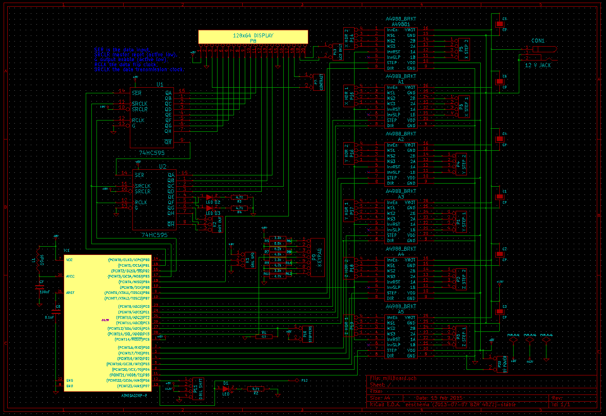
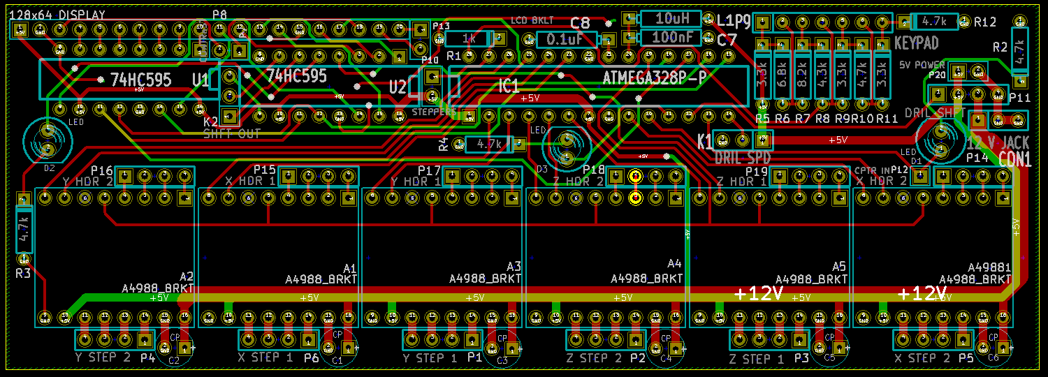
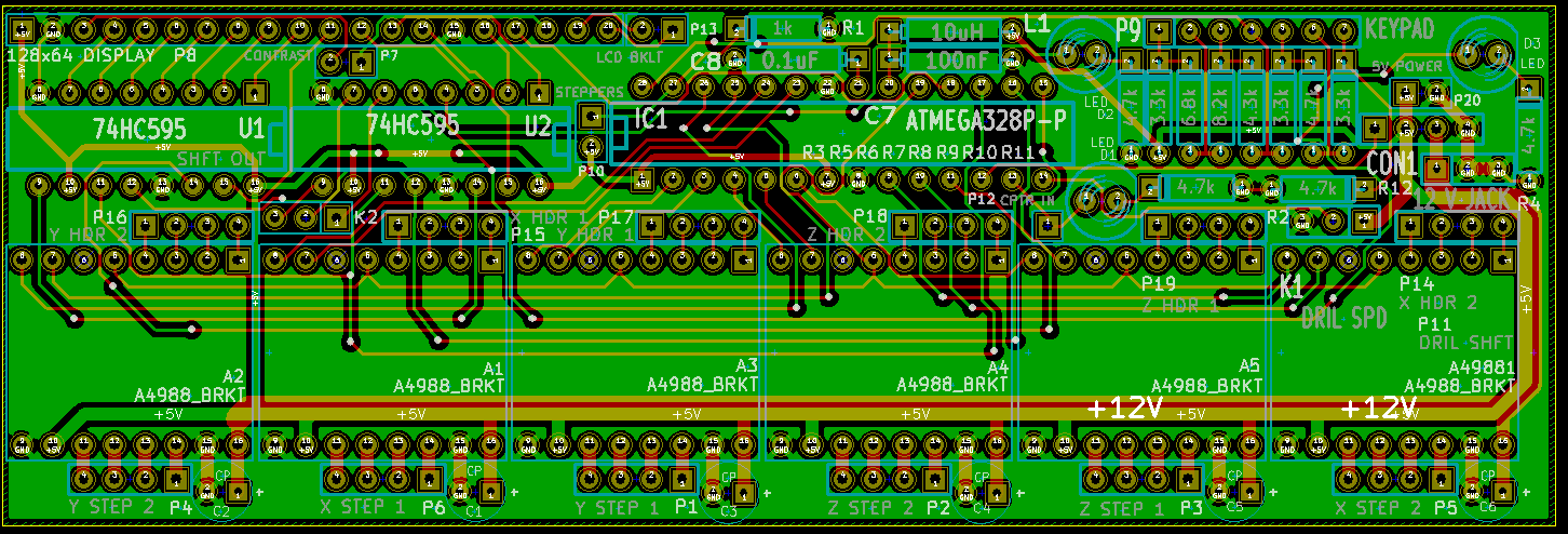
To construct the electronics board, I prototyped a PCB with KiCad and send the design out for manufacturing to OSH Park. Because OSH Park charges for the total rectangular surface area used, I attempted to collapse a 12-pin keypad, a 128x64 LCD display, six stepper motor drives and an ATmega328P-PU microcontroller all on the single board. To support all of these devices, I also used a few serial-to-parallel chips to increase the total number of I/O pins available.
Pins required:- Six stepper motor drivers: 1 (reset) + 6*2 (direction + step) = 13 (output)
- Drill Bit PWM: 1 (speed selection) = 1 (output)
- Drill Bit PWM speed indicator: 1 (actual drill bit speed) = 1 (input)
- 12-button keypad: 1 (current button press value) = 1 (analog input)
- General-purpose potentiometer: 1 (current dial value) = 1 (analog input)
- Computer input line: 1 (data input) = 1 (input)
- 128x64 display: 8 (data lines) + 2 (chip selection) + 3 (reset / clock / command (or) data) = 13 (output)
- Status LEDs: 2
- Total: 33
- Each stepper motor driver has two headers -- one to swap out the motor, the other to swap out the driver.
- Each stepper motor driver has it's own transient protection capacitor on the 12 V line.
- The ATmega has additional passive components to reduce the noise on the analog reference 5 V line.
- The keypad uses a resistor network to uniquely identify each key (which creates a short on two of its pins), to significantly reduce the pin count to 1.
PCB Design
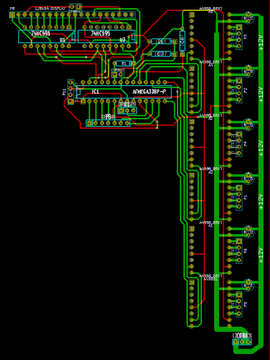
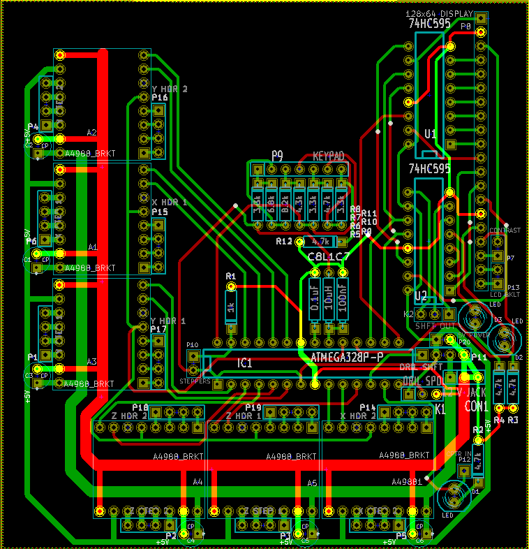
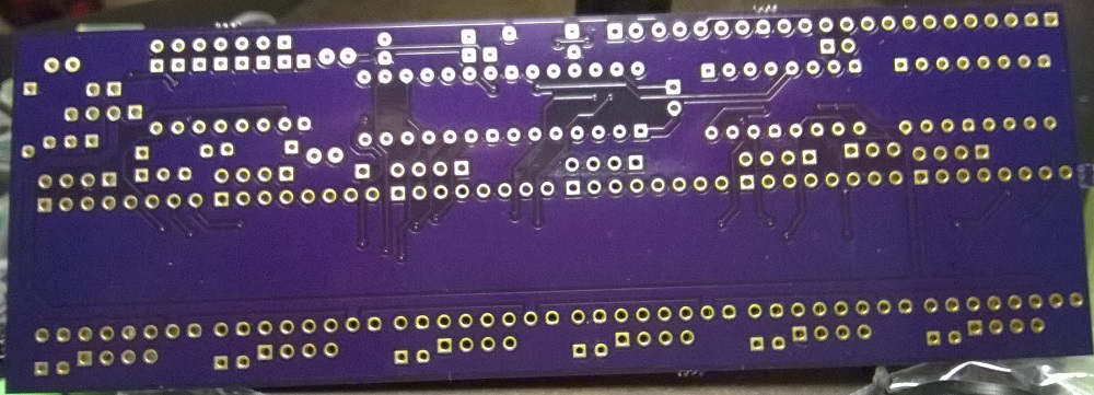
Resulting board
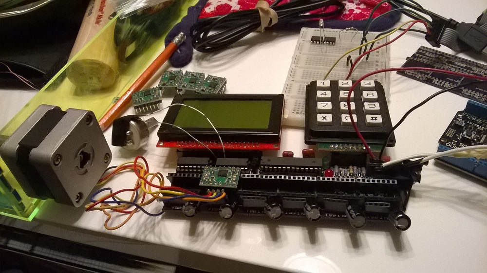
After about a month of lead time, I received the order I had submitted.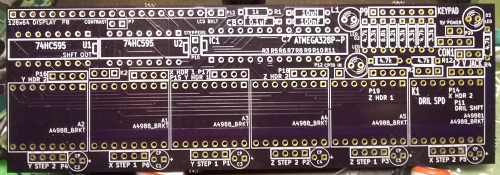
Testing
I went through two main phases testing these boards -- mechanical and electrical -- to verify the operation of the device.
Mechanical Design Errors
- Major: The stepper-motor sockets were all 1-pin spaced too far apart (oops). Pins fit when bent.
- Minor: The capacitor pads were too small, so all the capacitors were placed sideways.
- Minor: The LCD covers the backlight pads -- which was OK, because I wasn't planning on using the backlight.
- Minor: I used the wrong sized-pads for the keypad, so it only accepts smaller pin sizes -- such as the pin sizes the keypad happened to have.
Electrical Design Errors
Although the mill was functional, the ATmega328 microcontroller had a hard time running the whole operation at a reasonable rate.
End result